


App Description
We usually Need to maintain Inductance with Capacitance parameters to get actual Resonant frequency for electronics usage. So this app helps us to calculate resonant frequency so that tuning will be easier for radio etc.This app also helps us to educate resonant frequency and its concept. Analysis of RLC circuit is now easier with this app.
Thus far we have analysed the behaviour of a series RLC circuit whose source voltage is a fixed frequency steady state sinusoidal supply. We have also seen in our tutorial about series RLC circuits that two or more sinusoidal signals can be combined using phasors providing that they have the same frequency supply.
But what would happen to the characteristics of the circuit if a supply voltage of fixed amplitude but of different frequencies was applied to the circuit. Also what would the circuits “frequency response” behaviour be upon the two reactive components due to this varying frequency.
In a series RLC circuit there becomes a frequency point were the inductive reactance of the inductor becomes equal in value to the capacitive reactance of the capacitor. In other words, XL = XC. The point at which this occurs is called the Resonant Frequency point, ( ƒr ) of the circuit, and as we are analysing a series RLC circuit this resonance frequency produces a Series Resonance.
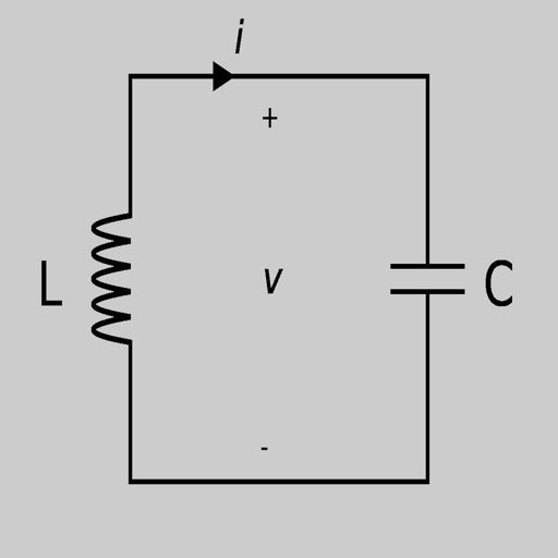
Series Resonance circuits are one of the most important circuits used electrical and electronic circuits. They can be found in various forms such as in AC mains filters, noise filters and also in radio and television tuning circuits producing a very selective tuning circuit for the receiving of the different frequency channels. Consider the simple series RLC circuit below.
Series RLC Circuit:Firstly, let us define what we already know about series RLC circuits.
However, as the frequency approaches zero or DC, the inductors reactance would decrease to zero, causing the opposite effect acting like a short circuit. This means then that inductive reactance is “Proportional” to frequency and is small at low frequencies and high at higher frequencies and this demonstrated in the following curve:
Inductive Reactance against Frequency:Inductive reactance against frequency.Therefore, inductive reactance is positive and is directly proportional to frequency ( XL ∝ ƒ )
The same is also true for the capacitive reactance formula above but in reverse. If either the Frequency or the Capacitance is increased the overall capacitive reactance would decrease. As the frequency approaches infinity the capacitors reactance would reduce to practically zero causing the circuit element to act like a perfect conductor of 0Ω.
But as the frequency approaches zero or DC level, the capacitors reactance would rapidly increase up to infinity causing it to act like a very large resistance, becoming more like an open circuit condition. This means then that capacitive reactance is “Inversely proportional” to frequency.
iPhone Screenshots
(click to enlarge)


App Changes
- November 05, 2019 Initial release
Other Apps From vlada shkuratova